Batteries and Charging

Split from General / Technical for discussion of anything electrical, electronic... 12v, Inverter, Satellite, Headlights, flashlights etc.
User avatar
Blue~Go
Senior Member
Posts: 3797
Joined: July 31st, 2014, 1:01 am
Location: 1999 Concourse

Re: Batteries and Charging

Post by Blue~Go »

No worries on my long negative/chassis ground post. It was just something for "if it helps."

On that "breaker" - it sure looks like a fuse to me. I would not keep it no matter what you do. This is just based on me looking up that brand/type and although I found the parent company, I could not find any actual data sheets. I only found them sold places like eBay. Not a great sign, to my mind. There are many makers of "Amazon" type fuses. I have seen them come to grief. These are important so you don't want "lesser" ones, or something you can't find the specs on.

If you do choose to keep it, buy those specific spare fuses and carry a couple spares. Also, you might want to check your Xantrex documentation, because my Xantrex 1500 calls for a 150a fuse. Guessing the Xantrex 1000 would call for a 100a fuse (yes, you are fusing for the wire, and your wire is plenty large, but sometimes device makers kind of do "double duty" and use it as a second line of defense for the device).

But....the inverter is your biggest single load by far. Why not use a known/rated/specced fuse (or breaker, though that will be more expensive). Or use one of the fuses already a part of the Safety Hub, as in my drawing. I would likely do that just because.... they are already there. Then you don't have to carry some completely different/unique type of spare fuses.

If you do want to use some different type of fuse, keep in mind that then you will want to stock and carry spares of that specific, different fuse type (I try to keep that to a minimum when planning, but it's certainly something you can do). Other fuse types you could consider:

These will all be AFTER the MRBF fuse and after the switch, so they don't need a specific AIC rating.

I've never used a breaker on my inverter and have never blown a fuse, but... you can if you want to.

Other possibilities. If your inverter just wants to be different ;)
ANL 100a fuse with ANL fuse block (similar form factor to what you have).
Mega 100a fuse with Mega fuse block (similar form factor to what you have)
Blue Sea 187 Series breaker, specifically 100a BS 7144 (this is a breaker)

Or if you do want to use a Midi fuse, like is in the Safety Hub, but you just want a separate fuse holder for some reason I can't see:

Midi 100a fuse in separate Midi fuse holder (this the identical fuse type as the ones already in the Safety hub).
1999 Concourse
deppstein
***Repeat Contributor***
Posts: 416
Joined: July 13th, 2015, 7:07 am

Re: Batteries and Charging

Post by deppstein »

My mistaking a fuse for a “breaker” only goes to reinforce the notion of my being “electrically challenged!”…warned you. And from an unreputable source no less. On your advice alone, I’ll get rid of it (once I learn how :). And I think I’ll go the simplest route and just slot it into the Hub with a 100 amp fuse.
I spent time yesterday and this morning playing with the layout in effort to understand how the concept might look in real space. I do a lot of this sort of building in my head (it’s how I came up with the idea of the high headlights and most of my woodworking designs). For this one though, since it new stuff for me, I’ll have to sketch it out. Rest assured, I’ll send you copy as soon as I have one for comments/suggestions. I think it involves a hard link between negative from Hub and Load end of Smart Shunt using the Blue Sea 9159 you mentioned. Sounds like I will also dump that current line out from battery that is probably ground (once confirmed) to be replaced with that new 4awg ground to chassis (in the hole).
…no turning back now!
deppstein
***Repeat Contributor***
Posts: 416
Joined: July 13th, 2015, 7:07 am

Re: Batteries and Charging

Post by deppstein »

OK...before heading off to Memphis, I couldn't resist putting together a Scope of Work Description and Rough Schematic of what I think things are going to look like. The Scope pertains to all of the work to be done, while the Schematic (attachment) is just of the distribution side of the battery bay where all the wires flow. I stayed up too late last night working to get it all down, so I am definitely expecting comments/corrections/questions. Plenty of time to change/refine things. Also--as you will notice, my schematic heavily relies on Blue's previous work in this regard...OK, I basically copied it!!! :)

Anyway, let me know what you think.
David

Eppstein Chinook Electrical Upgrade Scope of Work
Equipment:

--Victron Orion XS (Eddie purchase)
--Victron IP22 Charger 12/30 (Eddie purchase)
--Victron 6 awg cable kit for IP22 (Eddie purchase)
--Victron Temp sensor (Eddie purchase)
--Blue Sea Safety Hub 150 (David purchase)
--Victron Smart Shunt IP 21 300 amp (David purchase…needs for shim measurement)
--Blue Sea Battery Cut-off Switch 6004 (David purchase)
--Blue Sea 9159 Link Connector (David purchase)
--Fullriver dc115-12 Deep Cycle AGM batteries (2) (David purchase)
***M8 threaded posts (3) (Stainless) for Orion XS (Eddie or David purchase?)
***M6 threaded posts (2) (Stainless) for IP22 Charger (Eddie or David purchase?)

Battery Compartment Distribution Notes to Accompany Schematic

--Blue Sea Safety Hub to be oriented with POS to Battery at Top, with enough room at top and left side to comfortably attach wires. It will be mounted on the wall on right side of battery box Note: it will be shimmed to match height of IP21 Smart Shunt to facilitate attachment with Link Connector
--IP21 Smart Shunt will also be mounted on the right wall, to the right side of, or below the Hub, depending installer’s preference
--Blue Sea 6004 to be installed on Line from Hub to Battery POS
--Hole to be drilled in upper left corner of right wall to accommodate cables from the IP22 Charger mounted on the opposite side of the wall
--Orion XS Charger will be mounted on left side of the battery box wall

Miscellaneous Tasks

--Remove existing Blue Sea 7622 Separator (David)
--Put new terminals on Start battery (David)
--Eliminate LVD (David)
--Run new 6 awg wire direct from distribution panel in Rig to POS of battery (David)
--Remove wires from PD4645 from Charge Breaker and replace with new wires for outlet used for IP22; mount new outlet inside RV close to battery box (David)
--Identify all wires currently into POS battery…remove those no longer needed (David)
--Remove Inverter Fuse and put 1/0 wire ends back together (Eddie?)

Wiring (Eddie)

--Wire ORION XS by running new pair of 4awg wires from Start battery, through Orion XS, and onto Hub POS and NEG Posts. Fuse POS of Orion at Start battery with 60 amp MRBF
--Wire IP22 Charger to POS and NEG posts of Hub using 6awg Victron wire kit—Note: will have to modify one end of cable kit with rings to fit M8 terminals on Hub
--Run new 4awg ground from Hub NEG to chassis ground via hole in bottom of battery compartment
--Wire IP21 Smart Shunt to Negative Hub side using Blue Sea link connector to Load side and 1/0 wire from Battery side to NEG Battery; Also install Temp Sensor!
--Wire POS from Hub to POS of Battery using 1/0 wire; add Blue Sea Cut-off to the run, and fuse at POS battery terminal with 250 MRBF
Attachments
Eppstein Chinook New Wiring Schematic.jpg
User avatar
Blue~Go
Senior Member
Posts: 3797
Joined: July 31st, 2014, 1:01 am
Location: 1999 Concourse

Re: Batteries and Charging

Post by Blue~Go »

That looks pretty good! Nice. Ha, I'm used to looking at/installing the safety hub in one orientation (small fuses on "top") and all of a sudden here is yours, "sideways." But I adapted.

A note is just that you may not want to end up using a hard link from shunt to Safety Hub negative bus. I guess it depends on how compact you need it to be, but it could somewhat block "access" for your negative wires. Or not. Just now that you may want to use a cable for that one.

Also, I've only mounted shunts for BMV's, not the Smart Shunt (and even then, there is the regular SS and the IP65 version). So it may turn out that you need space for where the temp sensor leads or etc. go into the shunt (so again you may want it slightly further away than a bar would allow, but see how it goes).

Also note you can perfectly well run the inverter negative 1/0 cable to the Safety Hub negative bus and not to the shunt load side. I drew it on the shunt just to show that -- if need be -- you *could* put one negative wire on the shunt along with the main feed wire. It kind of depends how it works out in real life. Sometimes once you start actually putting in cables you might find that cables or lugs would work out better in a little different orientation (but same electrically).

Nice going.
1999 Concourse
User avatar
Blue~Go
Senior Member
Posts: 3797
Joined: July 31st, 2014, 1:01 am
Location: 1999 Concourse

Re: Batteries and Charging

Post by Blue~Go »

deppstein wrote: February 2nd, 2025, 11:33 am OK...before heading off to Memphis, I couldn't resist putting together a Scope of Work Description and Rough Schematic of what I think things are going to look like.
Just a few notes as I read through your lists.
deppstein wrote: February 2nd, 2025, 11:33 amEquipment:
--Victron IP22 Charger 12/30 (Eddie purchase)
Note that there is an IP22 30-1 and an IP22 30-1. The -1 should be less expensive, and the connector area is less cluttered. I can't think of any reason you would want the -3.
deppstein wrote: February 2nd, 2025, 11:33 am --Victron 6 awg cable kit for IP22 (Eddie purchase)
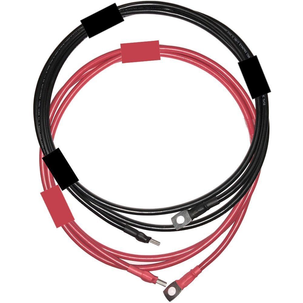
I don't know what this is. A cable kit? What makes it a kit? Guess I'll have to look it up. (Normally I would just use good, 6AWG marine boat cable, such as Anchor or equivalent.)

Is it this?

Image

If so I have to say it seems unnecessary. Plus... it is tinned cable? US UL-1246 spec cable (vs. unknown/mm)? Why does one need a kit? How would the cables happen to be the right lengths? Eddie surely has spools of proper boat cable and good tinned lugs (say FTZ power lugs)?

deppstein wrote: February 2nd, 2025, 11:33 am --Victron Smart Shunt IP 21 300 amp (David purchase…needs for shim measurement)
I would likely use a cable connection here. But also now I'm back to search because I didn't even know they made a smaller, 300a shunt (typical is 500a). Don't see it but it should be large enough.

Do make sure to add an alarm buzzer and a wire pair to run from the shunt up into say your overhead TV area to your shopping and to-do list. The battery monitor alarm is going to be your new LVD and if there is no buzzer well.... no alarm. This is needed because you aren't getting a BMV 712 (has shunt plus head and built in buzzer). I'm still not sure why one would prefer the smart shunt in your system, so I'm curious if you want to say.
deppstein wrote: February 2nd, 2025, 11:33 am ***M8 threaded posts (3) (Stainless) for Orion XS (Eddie or David purchase?)
***M6 threaded posts (2) (Stainless) for IP22 Charger (Eddie or David purchase?)
Okay, now you have me: How are "threaded posts" going to be used in the installation of either an IP22 or Orion XS. I've installed a number of these and cant' think where threaded posts would enter the picture? I may have a comment about stainless vs. tinned copper but that depends on where these things go, which I can't think of. Must know!
deppstein wrote: February 2nd, 2025, 11:33 am --Blue Sea Safety Hub to be oriented with POS to Battery at Top, with enough room at top and left side to comfortably attach wires. It will be mounted on the wall on right side of battery box Note: it will be shimmed to match height of IP21 Smart Shunt to facilitate attachment with Link Connector
Okay, I've already mentioned that as much as I love link connectors, this is not a place I'd use one. On top of the other reasons, the link is thick and will take up quite a bit of space on the shunt "screw." But maybe it's just because I can't see what you are doing.

Also, no big deal but just as an aside, the label panel on the Safety Hub cover won't be right side up (it's right side up when pos to battery is on the left).
deppstein wrote: February 2nd, 2025, 11:33 am--Hole to be drilled in upper left corner of right wall to accommodate cables from the IP22 Charger mounted on the opposite side of the wall
You may already be planning this but what I like to do is first buy or select a grommet for the hole, and then drill the hole to fit said grommet.
deppstein wrote: February 2nd, 2025, 11:33 am --Identify all wires currently into POS battery…remove those no longer needed (David)
Oh yeah! Do toot a few horns as you loft the LVD into the dumpster :lol:
deppstein wrote: February 2nd, 2025, 11:33 am--Remove Inverter Fuse and put 1/0 wire ends back together (Eddie?)
Hopefully you can just land the inverter side of that cable on the Safety hub with no butt connector needed. Guess you will see.
deppstein wrote: February 2nd, 2025, 11:33 am--Wire IP22 Charger to POS and NEG posts of Hub using 6awg Victron wire kit—Note: will have to modify one end of cable kit with rings to fit M8 terminals on Hub

Still wondering why? Why buy a kit of probably metric cable and then have to cut those ends off anyway when you can just use good UL-1246 rated fine-stranded, tinned copper boat cable? Surely Eddie would have this in his van shop (or you can order it easily).
deppstein wrote: February 2nd, 2025, 11:33 am --Wire IP21 Smart Shunt to Negative Hub side using Blue Sea link connector to Load side and 1/0 wire from Battery side to NEG Battery; Also install Temp Sensor!
I know, I know, I've already mentioned to maybe not use the Link here.

By the way, just in case you read about this somewhere. You may see people with uber modern Euro type vehicles saying oh you can't run negative from Orion XS right to battery negative. You must run it to chassis ground. That's apparently because these newer vehicles (as opposed to our stalwart Chinooks) apparently have some computer thingie inline in the negative cable that goes from the start battery negative to the chassis, so that's not a valid path. We definitely don't have that - I removed that little negative wire to make it a larger wire and.... it's just a wire. So you should be fine just running your 4AWG pair to the start battery. Just thought you might read that somewhere and wonder.
1999 Concourse
deppstein
***Repeat Contributor***
Posts: 416
Joined: July 13th, 2015, 7:07 am

Re: Batteries and Charging

Post by deppstein »

No wonder you are confused about my “threaded posts” comments regarding the Orion and IP22! Obviously, know not of what I speak! I thought that those pos/neg entry points accepted threaded posts—I see now that they are insert points! So, there goes my idea of also using the Orion neg for both the run from start to Orion and Orion to Hub. Given limited neg points on the Hub I was trying to minimize connections. Oh well…now am exploring how I can safely and reasonably double-up by replacing screw with stainless m8 threaded posts for the two end neg connections—one to accommodate the solid link (yes still think I need that given space limitations on that battery compartment wall)…that is still being evaluated) and the other end neg to double-up.
Thanks for heads up on IP1 (yes, getting that one).
Also, good call on just cutting cable instead of kit—the kit is for m6, so does me no good at all!
Regarding orientation—I feel like I have to lay things out so POS from Hub comes out toward the door of the compartment due to fact that cut-out switch will be on that line and I want to be able to access it easily.
…but, as I said, I’m still cgitating on all the placement and orientation stuff and will have more to say on that when I get back from Memphis.
About solid link…current thinking is that cable would have to be too long to fit everything in…we’ll see.
Finally, had not seen mention of issues with direct connection on newer Rigs—certainly right—no problem there, huh!
Oh—yes, I hear you on the alarm and grommet!
David
User avatar
Blue~Go
Senior Member
Posts: 3797
Joined: July 31st, 2014, 1:01 am
Location: 1999 Concourse

Re: Batteries and Charging

Post by Blue~Go »

deppstein wrote: February 3rd, 2025, 6:32 am No wonder you are confused about my “threaded posts” comments regarding the Orion and IP22!
Glad we got that figured.
deppstein wrote: February 3rd, 2025, 6:32 amSo, there goes my idea of also using the Orion neg for both the run from start to Orion and Orion to Hub. Given limited neg points on the Hub I was trying to minimize connections. Oh well…now am exploring how I can safely and reasonably double-up by replacing screw with stainless m8 threaded posts for the two end neg connections
What "screw" are you trying to replace. I'm confused again.

I'm also not sure what you are talking about doubling up. Maybe something with the Orion negative? Here is what I envision:

1) Positive red 4AWG cable starts on new MRBF holder/MRBF fuse on start battery positive
2) The other end of that cable goes into "IN" terminal on Orion (definitely cannot double anything in that terminal!)
3) Another piece of red positive 4AWG comes out of "OUT" terminal on Orion and goes to a Midi fuse position on the Safety hub

4) Negative black 4AWG cable runs from Start battery negative post to a negative post on the Safety Hub
5) A different black 4AWG cable runs from the Orion negative to the Safety Hub negative bus.

Now, if your Orion was way out in the middle of a long wire run (I have that on another setup, not my Chinook), THEN you would not run two separate negative legs, because you'd be needlessly doubling up on a long 4AWG wire. So then you might put a powerpost just next to the Orion negative and "interrupt" that long 4AWG cable with two ring lugs both of which would land on the powerpost stud. Then another short cable would go from the powerpost stud to the Orion. It's more connections and a bit of a pain, but makes sense if the Orion is in the middle of a long run.

BUT, your Orion is NOT in the middle of a long run. You just need a "loop" that is all 4AWG. So you can simply run the long 4AWG from the Start Negative post to the SH negative bus. And then a short (cuz Orion so close to Safety Hub) second 4AWG jumper from Orion to (any) negative post on the Safety Hub. Now you have a full 4AWG "loop" and no fiddling with power posts (or, god forbid, trying to do some weird screw into the Orion terminals - do not do that!). This is the thing that makes negative runs a little more flexible than the positive runs - the fact that negative is "common" and all ends up in one big pot.
deppstein wrote: February 3rd, 2025, 6:32 am—one to accommodate the solid link (yes still think I need that given space limitations on that battery compartment wall)…that is still being evaluated)
Fair enough. You can make a pretty short cable, but no worries considering the link. I just thought that it might almost get in the way, plus you only have so much "screw" length on those big 3/8" screws that go into the shunt (unless they have changed that). The link is thick.
deppstein wrote: February 3rd, 2025, 6:32 amThanks for heads up on IP1 (yes, getting that one).
Good! I did buy a -3 one time a couple years ago just because we was not able to get the -1 and my buddy I was helping out had time constraints. It's totally workable, but the connection area is more cluttered and I would have preferred the -1

Note: I can't see that there would be any left on the market now (but maybe if you were buying off eBay or something), but there was a Version 1 of the IP22. You definitely don't want that as it cannot do Smart Network and there is no way to upgrade it to be able to. Version 2 (looks just the same; came out a couple years ago IIRC) does do Smart Networking. So I can't imagine any real Victron dealer would be selling the Version 1 unless it was really cheap and they made it clear.
deppstein wrote: February 3rd, 2025, 6:32 am…but, as I said, I’m still cgitating on all the placement and orientation stuff and will have more to say on that when I get back from Memphis.
Understood! I've been thinking about making some mods to my electrical system, and I made paper cutouts of components (or used the real ones if on hand) and have laid them out oh, about 3,000 times to try different options :D

Oh, do note that (if it helps) you can usually run a cable out the top or bottom of one of the Blue Sea switches, even though typically you'd run out one side or the other. In case that helps your layout. Also, since it's just an On/Off switch, it could be "backwards" if that helps. I mean, either wire can go to either post.

Have a great Memphis trip!
1999 Concourse
User avatar
Blue~Go
Senior Member
Posts: 3797
Joined: July 31st, 2014, 1:01 am
Location: 1999 Concourse

Re: Batteries and Charging

Post by Blue~Go »

Okay, you know how sometimes I'm like a broken record? Heh. Here I go.

Note that if you have a good reason, obviously nevermind. But I'm still puzzled about why you want the Smart Shunt over the BMV 712 (which is also very Smart; it's just not in the name).

The shunt is basically the same (except the Smart shunt is a little bulkier cuz there is stuff attached to the side of the shunt -- in your cramped location).

For your system, I can't see anything the Smart Shunt would do that the BMV 712 does not do.

The BMV 712 display head (which you can just zip tie in the overhead or velcro to the couch wall behind the backrest so it's right by you or something) - I mean no need to cut hole and "install" if not desired - mine is not "installed.")

The BMV 712 display head requires no additional wire or wiring for a separate buzzer - the buzzer is built into the display head, which just clicks into the shunt and the display head with a phone cable type "click" connector (30' cable comes with it).

The BMV 712 has a relay, though probably you would have no use for it so that's probably moot.

The BMV 712 display head gives you info, just in case your phone is not handy or somehow isn't pairing or something (not saying that's too likely).

Here is the big one for me: So the alarm will now essentially be your LVD whichever shunt you choose. And you could set it for a super low voltage so the alarm would mean basically "you're done, shut it all down until you can recharge the batteries."

But since it's NOT an inflexible ancient LVD, you can set it for a different level. I have mine set for around 40% SOC. Now I rarely get this low, but if I do, it's not like "Sorry you shall be dark and cold for the rest of the night and then suffer in the morning when you get up, too" but rather "hey, getting low, make SURE you get some charge in sometime tomorrow" (like after morning heat and coffee/breakfast). Of course the levels are adjustable so you can decide and/or change it anytime.

Where am I going with this? (Cuz the last paragraph applies to the Smart Shunt alarm also).

Well mine has gone off maybe three times. Of course it's ALWAYS at 3 a.m. (because the batteries are normally charging during the day). Each time I'm so glad that I don't have to fumble for my glasses, find my phone, get that up and going, open Victron Connect, wait for the Bluetooth to connect, and THEN (and only then) find the menu/button and shut the darned alarm off. Everyone is awake now!

Nope, instead I can just reach for the display head and press the button. No glasses needed as the display illuminates when the alarm is sounding (to make it easy to grab, otherwise it's dark) and the button can be pressed by feel. Ahhh, back to sleep. I probably would still have been trying to get my glasses on with the Smart Shunt.

BTW, I found the 300a Smart shunt now. The BMV 712 comes with a 500a typical shunt, but that shouldn't really matter either way to you.

Prices:

Smart Shunt that you showed yesterday: $70
Floyd Bell buzzer (tho I'm sure you could use a different one): ~$25
Wire/crimps/etc. to run between them: ~$20?
Total: ~$115

BMV 712: $149

So a little more money for the BMV 712, granted -- but then less labor to install it than the separate shunt, wires, buzzer so maybe you claw a little back.

For me the main things are these:

1) Backup in case my phone isn't handy or Bluetooth has gone wonky (not that the actual bluetooth goes wonky but sometimes you could have a temporary pairing issue or etc. - it happens and is not always "Victron's" fault).

2) Someone else could look at the display if you wanted them to (and they had no paired device handy)

3) THE 3AM ALARM! (main reason!)

4) I don't use the relay function but might in future.

#3 is by far the main one though. HAS HAPPENED. I just hate being woken up in the night and then having to fiddle around for 5+ minutes including staring at a bright screen. Then I'm "awake" and can't just go back to sleep like I can with a 5-second interruption that also involves no bright screens, no glasses, etc.

I shall pull the needle off my broken record now :mrgreen:
1999 Concourse
deppstein
***Repeat Contributor***
Posts: 416
Joined: July 13th, 2015, 7:07 am

Re: Batteries and Charging

Post by deppstein »

...Back from Memphis and picking up where we left off.
Having had a few days "off" has given me time to digest previous comments and do some tweaking to my plan. To wit:
--I have abandoned the idea of the solid connector from the Safety Hub to the Smart Shunt. Thanks Blue for pushing on this...the solid is indeed to thick to work with both the shunt and Safety Hub (which is why I was playing around with the "bad idea/don't do that" notion of replacing the negative screws on the Safety Hub with threaded posts to try to acomodate the added depth needed). A wire connection will work much better, and with ring connectors, I will be able to put the connector wire (have determined that 4awg is sufficient)...see below) and the 4 awg neg wire to chassis ground on the same screw. In same fashion, I will have room on the Load side of the Smart Shunt for 4awg connector wire and the 1/0 inverter negative...easier to connect this to Shunt than Safety Hub...also by attaching it directly to Shunt, it allows me to use 4awg wire for connector rather than 1/0. And 4awg is sufficient because the IP22 and Orion will never be working at the same time, so negative load through the Safety Shunt will never exceed capacity of the 4awg neg connector. With this modification, I believe that everything will fit nicely on the Safety Hub.
--Smart Shunt vs. the BMV 712...have decided, after reading, re-reading, and considering my particular needs to stick with the Smart Shunt 300. Reasons:
--smaller...size in battery box is at a premium
--the BMV 712 has a different temp sensor set up, and I have grown to understand and like the temp sensing set up on the Smart Shunt (plug and play)
--Yes, I will need to buy and run a separate low voltage alarm from battery to cabin with the Smart Shunt...but would have do run the dial of BMV 712 as well...so seems like a wash here to me.
--The Start Battery to Safety Shunt Negative run will be as Blue describes
--The Positive runs from Start Battery to Orion and from Orion to Smart Shunt will be as Blue describes.
--And there will be another Negaitve run from Safety Hub to new ground, as described.

So, that's my latest plan. Feeling good about it, but, of course, open to any and all comments/suggestions!
David
User avatar
Blue~Go
Senior Member
Posts: 3797
Joined: July 31st, 2014, 1:01 am
Location: 1999 Concourse

Re: Batteries and Charging

Post by Blue~Go »

deppstein wrote: February 8th, 2025, 7:45 am ...Back from Memphis and picking up where we left off.
Having had a few days "off" has given me time to digest previous comments and do some tweaking to my plan. To wit:
Well no-one can say you are not a quick study 8-)

Couple of questions/thoughts still:

1) I think not using the solid Link is a good idea in this case. Glad you changed.

deppstein wrote: February 8th, 2025, 7:45 am A wire connection will work much better, and with ring connectors, I will be able to put the connector wire (have determined that 4awg is sufficient)...see below) and the 4 awg neg wire to chassis ground on the same screw. In same fashion, I will have room on the Load side of the Smart Shunt for 4awg connector wire and the 1/0 inverter negative...easier to connect this to Shunt than Safety Hub...also by attaching it directly to Shunt, it allows me to use 4awg wire for connector rather than 1/0. And 4awg is sufficient because the IP22 and Orion will never be working at the same time, so negative load through the Safety Shunt will never exceed capacity of the 4awg neg connector. With this modification, I believe that everything will fit nicely on the Safety Hub.
I am probably confused here (because.... words), but just to make sure you are not planning to use 4AWG anyplace that is fused as part of a 1/0 run. By that I mean the wire from the MRBF on the house bank to the "in" terminal on the Safety Hub, and also the negative wire from the house bank to the shunt "battery" terminal.

I would probably still run a 1/0 wire from the Safety Hub negative bus to the Shunt "load" terminal.
deppstein wrote: February 8th, 2025, 7:45 amSmart Shunt vs. the BMV 712...have decided, after reading, re-reading, and considering my particular needs to stick with the Smart Shunt 300. Reasons:
--smaller...size in battery box is at a premium
Okay I'm going to have to look up that 300a Smart Shunt. Because the 500a ones are simply the same shunt from the BMV, plus the added "smart parts" stuck onto the side of it (that would be in the head on the BMV). Maybe the 300 is that much smaller? I'm going to look.
deppstein wrote: February 8th, 2025, 7:45 am--the BMV 712 has a different temp sensor set up, and I have grown to understand and like the temp sensing set up on the Smart Shunt (plug and play)
The BMV temp sensor is totally plug and play. Two metal pins push and lock into the shunt (they provide it power, and sense the temp, so no separate power wire is required). On the battery side it's a lug that's already part of it that you put on the battery terminal. I'll take a look at the SS ones, but I don't see how they could be more plug and play.
deppstein wrote: February 8th, 2025, 7:45 am--Yes, I will need to buy and run a separate low voltage alarm from battery to cabin with the Smart Shunt...but would have do run the dial of BMV 712 as well...so seems like a wash here to me.


Fair enough on that point.
deppstein wrote: February 8th, 2025, 7:45 am So, that's my latest plan. Feeling good about it, but, of course, open to any and all comments/suggestions!
David
I'd say it's evolved nicely from first concept!
1999 Concourse
Post Reply