3 electrical systems

Split from General / Technical for discussion of anything electrical, electronic... 12v, Inverter, Satellite, Headlights, flashlights etc.
chin_k
**Forum Contributor**
Posts: 2257
Joined: June 26th, 2017, 9:38 pm
Location: Southern CA

Re: 3 electrical systems

Post by chin_k »

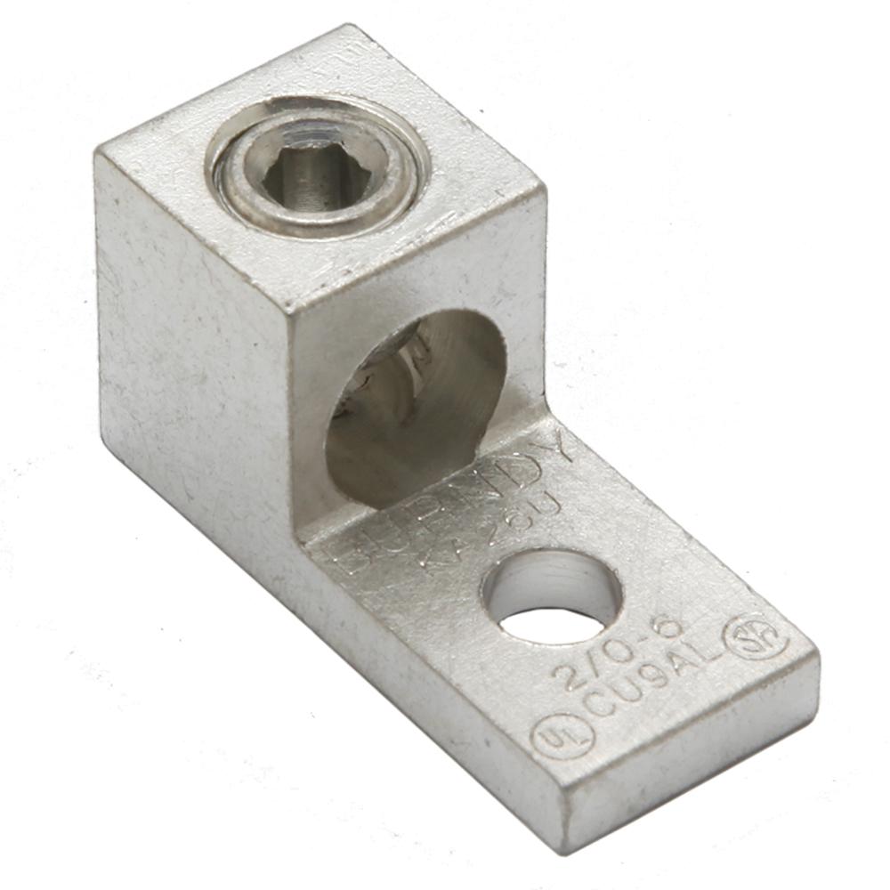
I am sure you see these "mechanical" lug all the time.
Image

They are not used on boat (and other applications) since it is easy for water to get between the wire and the screw/lug, and it is difficult to waterproof with a shrink tube. Once the junction is contaminated, it will corrode really fast.
2000 Concourse dinette, on 1999 6.8L Ford E350 Triton V-10 Chassis
Riste
Posts: 57
Joined: July 26th, 2015, 9:37 am
Location: Venice, FL

Re: 3 electrical systems

Post by Riste »

Thanks,
Can they be used inside the coach?
Riste
1997 Concourse 460
User avatar
caconcourse
Senior Member
Posts: 510
Joined: October 31st, 2014, 10:25 pm

Re: 3 electrical systems

Post by caconcourse »

Riste wrote: January 24th, 2019, 11:29 am Thanks,
Can they be used inside the coach?
Yes.

Also note that these are the lugs used for all of the Chinook DC ground connections on the frame. They do degrade over time and the elements and should be checked regularly. However, they do the job.


They are also used for virtually every DC connection to the OEM and Progressive Dynamics-type power converter/charger or even in any breaker box or buss bar, so there is no reason to distrust them. The "looser" diameter of the wire hole in the lug is compensated somewhat by the fact that the set screw smashes the wire strands against the screw and walls of the hole. I would doubt that the conductivity difference between them and a crimp on lug is significant. Crimping has its own problems, and can come loose if not made properly. The best connection for large wire is probably a crimp with solder applied to join all the strands and the crimp.
Clay
2001 Concourse
Santa Barbara, CA
User avatar
Blue~Go
Senior Member
Posts: 3797
Joined: July 31st, 2014, 1:01 am
Location: 1999 Concourse

Re: 3 electrical systems

Post by Blue~Go »

I think the reason this type is not in the ABYC standards for boats is that it doesn't do well with vibration (for one reason). They would also be awful for corrosion, but inside a Chinook that's not as much of an issue (sure does get to those stock chassis connections though).

I've seen numerous accounts of people having issues with vibration/loosened/hotspots on the brown boxes, and that's just with smaller wires. They were used originally because the brown box is a cheap/fast all-in-one for an RV maker, not because it's ideal. Heck, some of the important wires aren't even provided with overcurrent protection (so not the best model to follow). I wouldn't use these, especially if your goal is to upgrade to a better, safer, more robust system.

If the reason you are considering them is to avoid making your own crimps, then I would recommend ordering the custom cables from someone like Genuine Dealz. Their ordering process is easy and clear, and they give good value. They use marine approved tinned copper cable and decent quality lugs and heat shrink. Sure, you won't be able to customize the lugs or change the length once you get them, but I think it would be the way to go over the screw/crush type you show.

PS: I am only referring to a proper crimp, so anything based on a lousy crimp isn't included in my examples.
Last edited by Blue~Go on January 24th, 2019, 2:01 pm, edited 1 time in total.
1999 Concourse
chin_k
**Forum Contributor**
Posts: 2257
Joined: June 26th, 2017, 9:38 pm
Location: Southern CA

Re: 3 electrical systems

Post by chin_k »

Clay did make some good points about the various mechanical lugs/connectors the rig has thru out the system. I completely forget about the fact that the ground connectors are using these. I still would go with the regular lug for permanent installation, however.

The following is a relatively informative white paper from Hubbell about the various connector types, and each of their advantage and disadvantages. The mechanical lug falls under the mechanical connector section 2.2.1.3, while the regular lug is the compression type on section 2.2.5

https://hubbellcdn.com/ohwassets/HCE/bu ... 180411.pdf
2000 Concourse dinette, on 1999 6.8L Ford E350 Triton V-10 Chassis
User avatar
Blue~Go
Senior Member
Posts: 3797
Joined: July 31st, 2014, 1:01 am
Location: 1999 Concourse

Re: 3 electrical systems

Post by Blue~Go »

chin_k wrote: January 24th, 2019, 1:58 pmI completely forget about the fact that the ground connectors are using these. I still would go with the regular lug for permanent installation, however.
One note is that corrosion problems with the chassis grounds have turned up many times in Chinook discussions. They are often discovered as the source of an issue. I added something about that in my previous post. Corrosion is not as much of an issue inside the Chinook (I forget if these batteries are out in the generator box or inside), but there are just a bunch of reasons that people on boats (and I imagine aircraft?) don't prefer to use those crush type screw connections. Poor contact, corrosion, and vibration coming to mind.

Chinook did a nice job with their electrical as compared to the era they were built and to other RV makers; but I would never hold it up now as a reason to put something together in a certain way. Even with their better than average work, wires are too small, wires aren't fused in some cases (they are too small to do so), crimps have no heat shrink and are basically the cheapest type, vibration prone connections are used, no corrosion protection on outdoor connections, etc.

Again, they did a nice job compared to some other RV's I've seen, but I just don't see using that as reasoning for how to do things now, IF one is setting out to make a better, safer, and more robust system. Also today we have better products, more access to information, and if doing our own work we don't have the time pressure of a production setting and having to punch a clock and say how many units we completed in X number of hours.
1999 Concourse
User avatar
caconcourse
Senior Member
Posts: 510
Joined: October 31st, 2014, 10:25 pm

Re: 3 electrical systems

Post by caconcourse »

You won't convince me that crimping is any more robust than these mechanical connections in our particular environment. Robustness factors include repairability and convenience factors, and crimps are virtually unrepairable by an average DIY'r without some expertise and proper tools, not to mention crimps. Tightening a loose set screw or clamp on the other hand is easy for anyone with an allen wrench or appropriate general purpose tool (screwdriver or crescent wrench, depending on the fastener).

I can tell you about a multi-million dollar failure of a military undersea system (unfortunately designed and manufactured by my employer) that failed due to one weak crimp that got yanked during the installation. This system was designed by mechanical engineers, built with calibrated tools and experienced technicians, but it was still faulty and the failure was catastrophic. It is not easy to know if a crimp is faulty, unless it is so terrible the cable comes out (and I've made quite a few of those).

I can't tell you how many jumper cables I have thrown away due to crappy crimping, or how many failed crimps I have encountered on everything from cable TV cables, Ethernet, butt splices, even battery cables, and I could go on. In reality, crimping is a cheaper manufacturing technique for mass production, not a more robust or expensive one.

I am not saying a good crimp is not good, I am saying that the chances that one of these mechanical lugs fails is not significantly greater, and when or if it comes loose, it is easily repaired with common tools. I can say I have never experienced a single problem with the DC connections in the Chinook that have set screw connections. I have had some crimped butt splices pull apart.

The grounding lug failures on the Chinooks are mainly due to the screws holding them to the frame rusting out, not due to a failure of the wire connection. As I recommended, these conneections should be inspected and repaired if needed on a regular basis. But a crimped on wire would not be any more reliable in this usage, corrosion will creep inside a crimp also and you still need a screw to hold it on.

Also as I noted, adding solder to a crimp will make up for many crimpling flaws by improving conductivity as well as mechanical strength.
Clay
2001 Concourse
Santa Barbara, CA
User avatar
Blue~Go
Senior Member
Posts: 3797
Joined: July 31st, 2014, 1:01 am
Location: 1999 Concourse

Re: 3 electrical systems

Post by Blue~Go »

We can each choose our own ways. I'm biased toward ABYC, as my experience is in boats (and seeing the failures of various other methods on them), and the ABYC's recommendations have done well by me (they do update them in various ways as the years go by - they are re-evaluated on a regular basis (for example right now they are re-visiting their fusing recommendations in light of the big "powerhouses" of lithium house banks that have become more popular. Back in the day people just weren't storing this much quickly releasable power on most boats -- or RV's).

That said, I will "disobey" them in certain circumstances. For example, they have an exception for fusing starting banks, since you clearly don't want a fuse to blow when you need to start your engine afloat. I do it differently by choosing a wire size that I can fuse high enough that that won't be a problem, because I like that wire fused. (But I think the rule came about due to very large engines that really couldn't be "over wired" in any sort of practical way.)

If soldering in a moving vehicle (vibration), I would say pay extra attention to mechanical support adjacent to the soldered joint (ABYC does allow soldered joints as an option, but specifies more support than a crimped connection, which is less troubled by vibration). They presume that whatever method is used will be a good example of that method (so they don't address bad solder techniques or crappy crimps).

I can see it seemed too much like I was trying to convince you to do it "my" way. I'll try to back off on that as I would rather simply provide information (but then I do like to say why, and that can come off as trying to convince, I agree).

Riste: I hope it's clear that you are free to choose any/all or none of our advice here. Don't just listen to me (not that I'm saying you were :lol: )

PS: I do hear you on being able to repair things with common tools. That's a good thing to strive for. But, a loose electrical connection can be a serious problem; it can make heat that will not blow a fuse. On boats that already have many of that type of terminal (and not practical to change), it's recommended to check/tighten them on a regular basis (every six months or more frequently if possible - some were always a little loose if done twice a year).

I have cut apart (and also seen photos of) good crimps on large wires. They actually "meld" the wire so it's not like strands and a crimp. It's like a solid piece (which makes you wonder why they are not as prone to vibration damage - I guess it's because the solid part doesn't extend as far outward as a soldered joint?). This presumes the relatively finely stranded wire such as boat cable.

I have also seen crimped joints literally fall apart. But these were "crappy" joints done by a simple hammer blow. I wouldn't recommend those.
1999 Concourse
Riste
Posts: 57
Joined: July 26th, 2015, 9:37 am
Location: Venice, FL

Re: 3 electrical systems

Post by Riste »

I really enjoy all of the input from all of the people that respond, lots of experience and examples.The more knowledge you get the better decisions you tend to make, plus I enjoy learning for learning sake.
I enjoyed reading the Hubble information (not sure what that says about me). It helps knowing which to use and why.
Looking back, somehow I never learned to solder. I think its time, it will help the crimped lugs and also on the DC wires.
It is interesting to look at how a boating background takes Blue one way while caconcourse comes from more of an industrial history (I assume).
A question that was overlooked, would you use loctite on a mechanical lug?
Riste
1997 Concourse 460
User avatar
Blue~Go
Senior Member
Posts: 3797
Joined: July 31st, 2014, 1:01 am
Location: 1999 Concourse

Re: 3 electrical systems

Post by Blue~Go »

If you are going with something like the FTZ power lugs, then no solder would be better. They basically "meld" the wire when properly done and so solder would just be more "stuff" in there instead of copper wire, which is not what you want. They are sized for just wire and the lug with nothing else in there.

Maybe other crimps are different and have extra space in them where you would want solder - I haven't used any of that type. (I think I have seen some you are supposed to solder too?).


BTW, if you liked reading the Hubbell paper, you might enjoy reading through the ABYC standards. They have them for just about any boat system. You may not be able to read the latest ABYC electrical info without signing up or paying for it, but there are previous copies free on the web. The basics haven't really changed much.

I totally get enjoying it :geek: :geek:

PS: Speaking of enjoying, I can't remember if I linked this above, and I'm on my way out the door. But about 3/4 of the way down he addresses solder with marine crimps (which shouldn't be used). He also has some good photos of how the wire "melds" in a good crimp. Example being the one on the left (the good tool for this is not even expensive). This is for wire up to 10AWG - admittedly the tool for large lugs is not cheap (but I always justify it by the fact that it's cheaper than hiring someone and now I have the tool).

The photos make it easy reading, IMO.

Also, I see he answered my question of how the "melded" copper of a good crimp connection compares to solder in terms of embrittlement. Because he does address "if you must solder" (heh, yeah, he's not a solder fan). He says to be VERY careful that no solder extends past the crimp band. Also you crimp first, and then once you have a good crimp you can solder over it if you like. But maybe there are industrial crimps that are made differently than those we use on boats.

https://marinehowto.com/marine-wire-termination/

Good crimp on left.png
1999 Concourse
Post Reply